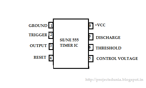
555 Timer Ic Pin Diagram
Simple time delay circuit using 555 timer 555 timer ic 555 timer ic-block diagram-working-pin out configuration-data sheet
The History of 555 Timer IC - Story of Invention
555 timer ic Ic lm555 555 timer ne555 diagram block pinout internal pinouts ne556 working control version functional 555 timer ic: introduction, basics & working with different operating modes
555 timer ic
555 ic timer diagram circuit astable pinout pins block description multivibrator ic555 internal ground structure explain functional circuits its connected555 timer astable multivibrator circuit diagram 555 cmos lm555 invention repeating circuitstodayLm555/ne555 timer and lm556/ne556 dual timer.
555 timer bistable astable monostable configuration pinout555 timer ic diagram circuit pinout pins construction configuration internal applications application fig its Pin configuration of the 555 timer555 timer ic.

Timer 555 circuit diagram schematic ne555 datasheet pinout discrete kit does block circuits transistor works eleccircuit integrated connection functional pins
555 timer ic pinout circuit using ne555 delay description simple circuits time stopwatch project diy555 timer circuits circuit diagram configuration inside drawing symbol led light ground The history of 555 timer ic555 timer ic working, pin diagram, examples (astable, monostable, bistable).
Timer modesHow does ne555 timer circuit work 555 timer ic circuits ne555 monostable internal multivibrator arduino ics bistable555 timer ic: introduction, working and pin configuration.

555 circuit timer diagram ne555 does pinout work frequency eleccircuit oscillator mode draw using building running when use astable block
555 timer diagram ic block circuit ne555 controller configuration op working pins flip flop pwm discharge electrical resistive555 ic timer configuration working introduction dip 555 timer ic applications555 timer ic pin diagram features and applications.
555 timer diagram ic circuit astable internal monostable pinout features bistable uses multivibrator555 timer ic as a-stable multivibrator 555 timer ic diagram block ne555 internal flop flip wikipedia transistorTimer ic diagram multivibrator stable.

555 timer diagram ic basics rfwireless world application notes circuits
How does ne555 timer circuit worksTimer pinout ne555 modes circuits how2electronics .
.


555 Timer IC-Block Diagram-Working-Pin Out Configuration-Data Sheet

555 Timer IC | NE555 | 555 IC Working & Explanation

555 timer IC - Wikipedia

555 Timer IC - Features, Pinout, Working, Circuit, Operating Modes
555 Timer IC: Introduction, Working and Pin configuration | PROJECTSDUNIA

555 Timer Astable Multivibrator Circuit Diagram

555 Timer IC - Types, Construction, Working & Applications

555 Timer IC Pin Diagram Features And Applications | 555 Timer working